
CONVEYING: Proceed with caution
Canadian Plastics
Raw Materials HandlingPellets barrelling at high speeds through pneumatic conveying systems can create holes, and then leaks, in even the most expensive stainless steel components. Applying the brakes to your conveying speeds can extend equipment life and reduce material waste in your plant.
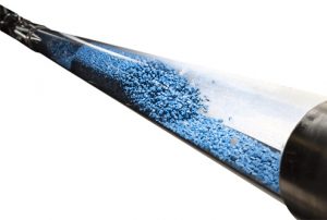
Photo Credit: Conair Group
Speed kills” has been a popular road safety slogan for decades, but it’s also appropriate for pneumatic resin conveying. As material moves faster, particles generate more heat, friction, and impact force, causing material degradation and contamination, pipe and elbow leaks, equipment and process failures, operational inefficiencies, added maintenance and replacement costs, and a shorter-than-expected lifetime for a resin conveying system.
So it’s no exaggeration to say that velocity-related conveying issues can kill your productivity. And as resin manufacturers expand the use of glass and other abrasive fillers that improve the useful properties of lower cost resins like polyethylene and polypropylene – but which will always abrade conveying system components and production equipment – the problem is probably getting worse. But it doesn’t have to. Understanding the impact of velocity on your conveying system, and controlling it, can greatly improve your chances for success, especially when moving abrasive plastics and those sensitive to degradation. Applying both basic and advanced velocity control methods will protect your investment, improve system uptime, and reduce maintenance.
THE GOLDILOCKS ZONE
As opposed to relatively low-speed dense phase pneumatic conveying – where the material is not suspended in the air stream – the plastics industry typically conveys with dilute phase, which conveys the material in suspension in the flowing air, and which can convey almost any material. Clearly, slower is better to avoid erosive wear, angel hair, and other related problems, but it’s not that easy: in dilute phase, high velocities have to be maintained. Optimizing dilute phase conveying velocity falls into what some conveying equipment manufacturers and suppliers like to call the “Goldilocks zone.”
For a conveying system to work, air in the pickup zone – the area where material enters the conveying line – has to move fast enough to sweep the pellets into the airstream from a standstill; air velocities below the pickup or saltation velocity will create instabilities in the conveying system, the worst being the inability to convey material from pickup point to receiver. “Some resins need a higher pickup velocity to get it out of the Gaylord and into the airstream than others, including filled resins, engineering resins, and some additives,” said Brian Davis, general manager of Maguire Products Canada Inc.
So what’s the acceptable speed range in the pickup zone? “The required speed varies with bulk density, pellet size, and pellet flow characteristics, but 35 to 40 mph is a minimum pickup speed for typical plastic pellets,” said Kevin Embury, vice president, engineered systems and business development with Novatec Inc. “Pellets continue to pick up speed as they move toward a receiver/separator, reaching speeds of 50 to 80 mph or more.” The ideal average conveying velocity for plastic resins that are susceptible to angel hair formation is about 4,000 feet per minute, equipment suppliers say. And with one or two exceptions – carbon black, for example – the same speeds hold true for powders. “I’ve never used different rules for conveying powders as opposed to pellets, since virtually all plastic tends to react to vacuum in a similar fashion,” said Rob Miller, president of Wittmann Battenfeld Canada Inc. The reason materials continue to pick up speed as they move closer to the receiver is due to vacuum, which is the pulling force created by the pump. When air first enters a conveying tube, there’s very little pulling force needed, and vacuum is low. As the air travels toward the pump, every foot of tube – and each pellet being carried – adds resistance to the air movement, so that the pump pulls harder, expanding the air so it moves ever-faster until it reaches the pump.
To reduce velocity, then, the temptation might be to choose a conveying tube size larger than needed to reduce vacuum, since less vacuum will “stretch” the air less and air speed will change less from start to finish as a result. In most cases, however, it won’t work that way. “Most standard pump packages already pull air at a pre-selected speed,” a technical paper from Novatec said. “If it pulls less vacuum, the unintended result is more speed at the pickup area.” Highlighting how excessive air speed can be an issue, one study showed that an elbow can last nearly 17 times longer when air speed is 35 versus 75 mph when conveying abrasives, and in this range, elbow life nearly doubled for every 10 mph decrease in speed. When conveying LDPE, another study showed steamer generation increased linearly with air speed in a 45 to 75 mph range.
KNOW YOUR OPTIONS
So there’s little doubt that controlling air speed is beneficial, and one of the simplest and easiest methods is a controlled air leak, usually created by adding a series of holes to the vacuum line before the pump safety filter. “The size and number of holes, along with operating vacuum, determine the magnitude of the air bypassing the conveying system,” the Novatec paper said. “An air leak that’s carefully con-trolled can reliably reduce system air speed by as much as 30 per cent.”
But keep in mind that the air leak steals air from the pickup area, the paper added, so it can cause problems if unplanned or poorly implemented. A second basic velocity control method, the Novatec paper said, is stepping the tube diameter to a larger size at a strategic point between the material source and the material destination. “By maximizing the large-diameter distance, speed decreases, along with resistance to movement, so the pump can carry more material,” the paper continued. “The key is understanding how resistance builds in the conveying line and how it affects the air speed throughout the entire distance material travels.”
One solution for controlling conveying velocity that’s made an impact lately is Conair Group’s Wave conveying system, a dilute phase system that can also operate in a dense phase mode. “While the 5,000-plus-feet-per-minute speed of dilute phase conveying has been the preferred method of material conveying for decades, it was never ideal for some sensitive resins,” said Rich Shaffer, Conair’s vice president of product development. Wave technology uses controlled-speed conveying of between 300 to 2,800 feet-per-minute to move these more sensitive materials, Shaffer continued. “It controls material speed and density, separate from air speed or air pressure, by blending conventional conveying components – a variable speed vacuum pump, tubing, bends, dust collectors, standard receivers, and surge bins – with an FLX-128 Plus controller and special air valves,” he said. “Depending on the existing conveying piping configuration, the Wave conveying system not only provides dilute phase conveying with controlled speeds, but adds one or two slower-speed conveying modes that prevent resin damage while typically increasing throughput.”
And Novatec has a series of air flow regulators designed to maintain the velocity of vacuum conveying air at optimum levels, which can slow the speed of the resin being conveyed during situations where there’s a lack of material volume in the conveying lines – such as line purging – to reduce issues like angel hair and tuning wear caused by abrasive materials; and also offers its FR-S flow reducer, designed for situations where vacuum pumps and line sizes are mismatched. “The FR-S can be used with line sizes from 1.5 inches to four feet in diameter, and either slows down an entire system if it’s placed at the main pump or isolates a receiver when it’s installed between a station selection valve and a receiver,” said Ryan Ismirlian, a Novatec conveying product engineer.
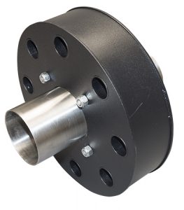
Novatec’s FR-S flow reducer. Photo Credit: Novatec
A QUESTION OF CONTROL
Traditionally, controls for pneumatic conveying haven’t been overly sophisticated: processors turned their pumps on and got what they got for air speed and material carrying speed and capability. But that was then. New advanced conveying controls allow conveying speed selection for individual stations to entire conveying lines for small processing plants. For example, the net5 system material conveying system from Wittmann Battenfeld can be used for the control of up to 24 mid-sized conveying systems. Control systems available from other equipment suppliers allow for pump RPM to be adjusted through a motor variable frequency drive, so air speed can be reduced for short distances or increased for heavy and other challenging materials.
Some controls can also vary speed during a single fill cycle, starting at full speed to accelerate material and then slowing to the target transfer speed; or slowing speed during a purge cycle as resistance dissipates. Another way of decreasing – or increasing – velocity for an individual station is with an air adjustment sleeve at the pickup point. “The processor can adjust that to see how the resin is flowing,” Brian Davis said. “But the right calculations need to go into it for this to work effectively.”
Indeed, the right calculations have to be made through-out – and these are the responsibility of the equipment suppliers. Designers consider both the conveying rate required to keep up with processes and the physical layout of the processing plant when choosing the required combination of tube size and pump to carry the load. But these designs aren’t always perfect, or get scrambled when changes are made later on. “A problem relating to too much conveying velocity usually isn’t the processor’s fault,” said Rob Miller. “While it’s certainly possible for the processor to make a mistake – such as opening a vent at the bottom of the silo – systems that convey at too much velocity either through a poor design out of the gate or due to additions and expansions without changing the line size are ultimately the fault of the system supplier.”
But even the best-designed, best-operated conveying system can be defeated at the very outset by out-of-control conveying velocity from the truck unloading system into the silo. “Stories we’ve heard about conveying velocity problems tend to blame the loading/unloading process – specifically the pressure discharge trucks, as their blowers can be ramped up quite high in order to unload quicker,” said members of Lorenz Conveying Products’ engineering team. According to Charles Williston, HammerTek’s national sales manager, this is a particularly difficult problem to solve. “A lot of customers try to prevent this by posting notes on the silos telling the drivers not to exceed a certain psi as they’re unloading the trucks, but the drivers don’t always pay attention,” he said. “The other option is to monitor the trucks from start to finish, but not all companies can spare a worker for that.”
ELABORATE ELBOWS
In addition to velocity management tools, appropriate component options should be considered to extend maintenance intervals and the overall life of the system. “When it comes to abrasion resistance, sometimes even velocity doesn’t fix that, so we go to materials of construction – ceramic line bends, glass bends, et cetera,” said Rob Miller. According to equipment suppliers, using surface-conditioned elbows provides improved protection against streamers and angel hair when conveying softer, heat-sensitive materials; for abrasive materials, meanwhile, glass elbows and extended-wear options on receiver stations can extend service life. And there are also a number of specialty elbows available that can enhance system operation and service life for both of these sensitive material types. “These enhancements are always a good idea,” said the Lorenz engineering team. “The upfront cost of using the right products for the conveying line will save money spent on repairs, downtime, and wastage later on.”
The Smart Elbow deflection elbow from HammerTek incorporates a spherical vortex chamber that extends partially beyond the 90° flow path, causing a ball of pellets to rotate in the same direction as the air stream, gently deflecting incoming pellets around the bend to eliminate elbow wear, friction, and product degradation. “In addition to preventing pellets from impacting the elbow wall, the vortex chamber causes the material to exit the elbow evenly and return rapidly to a laminar, steady-state flow within the conveying line,” said Charles Williston. “The airstream sweeps the vortex chamber clean after the material feed is shut off.” For processors plagued by damaged components in their vacuum conveying system or material contamination and plugged lines from angel hair and streamers, excessive conveying speed can be an obvious cause.
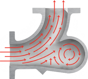
Hammertek’s Smart Elbow design. Photo Credit: Hammertek
Understanding the impact of velocity on conveying system operation can greatly reduce these issues, especially when moving abrasive plastics and those sensitive to degradation.
Speed doesn’t have to kill.